Basic Networking Components
Table of contents
Overview
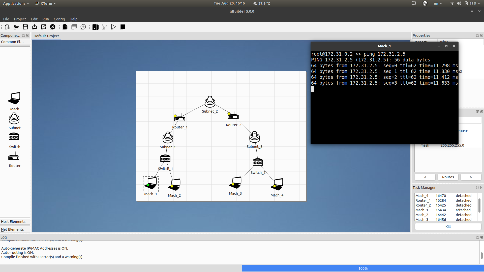
Using the tool gBuilder, user of Gini is provided with an intuitive graphical interface to build and test network topologies. Here is an example of a running topology with 2 connected LANs in Gini. The active terminal is how user can control each network device in the network. In the image below, host machine Mach_1 is sending pings to another host with IP 172.31.2.5, located in another LAN.
Host machine (Mach)
This devide represents a physical host computer in a network topology. Under the hood, each host machine is a Docker container running custom built images. The containers are lightweight and equipped with some UNIX network utilities like iproute2, ping, traceroute, tcpdump, iptables, etc. Using host machine in a topology, user can test network connectivity, speed, dump packets, configure and send custom packets, etc.
After starting, user can double click the host machine icon in the topology to attach to the machine’s terminal, where the mentioned commands can be used.
Layer 2 Switch
This device uses Linux bridge underneath to simulate the behaviour of a physical switch operating on Layer 2. The configuration of this device is handled entirely by Gini.
Router
This device acts as a Layer 3 switch to interconnect different Local Area Networks (LANs). gBuilder provides a command-line interface to configure a router device. From a router, you will be able to see the ARP table, ping other hosts in the network, and control the routing table.
Subnet
In addition to simulating physical devices in a interconnected network, the subnet device is a logical entity that identifies a local area network. Subnet devices must be added to each LAN in order to assign Layer 3 addresses to each host and router. Since automatic IP assignment is enabled by default, the user does not have to take further steps than adding subnet to a topology.
The topology in Overview is comprised of 3 LANs, each has its own logical subnet device. These subnets have different IP ranges, since bridging is not yet supported in Gini5.
Examples
Let’s use the network topology in the overview section for our example. Later on in the documentation, we will learn about other networking components of Gini5.
The complete topology, consisting of 3 Local Area Networks, looks like this:
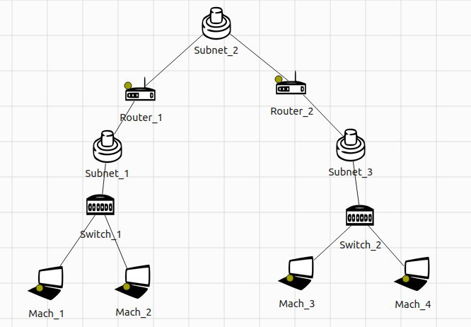
As stated above, each entity in this topology plays an important part in forming the interconnected of hosts and switches. Some devices are more special with a flickering yellow light. Those devices are “attachable”, which means you can double click their icons to open a command-line interface and configure the devices using the provided utilities. Attached devices will have a solid green light. And if for some reason a device is terminated while the whole network is up, a red light will be shown, and the device cannot be turned on again.
In order to see device-specific information, you can click their icons and look at the Properties and Interfaces menu on the right. For example, here is the information of Mach_4, some of which was auto-generated by the Gini5 compiler:
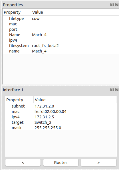
Note that, connected host devices must have exactly 1 interface, while routers can have more than 1.
Let’s try pinging Mach_4 and Router_1 from Mach_1. Open the command-line interface for each device by double clicking their icons. First, we need to get the devices’ IP addresses that Mach_1 can use:
| Device | IP |
|---|---|
Mach_1 | 172.31.0.2 |
Router_1 | 172.31.0.128 |
Mach_4 | 172.31.2.5 |
Inside Mach_1’s terminal, run the following two commands
$ ping 172.31.0.128
$ ping 172.31.2.5
and observe the result. Additionally, you can open Mach_4’s terminal and see the incoming packets by using tcpdump or tshark (tshark must be installed using the command apk add tshark).
After the ping experiment to test device connectivity, you can look at other tools or device configuration to understand how the network operates. You can look at the ARP cache, iptables chains, interface configurations, etc.